Gradient Background Image
 

Tech Matters

TECH MATTERSbailey Metal Processing Limited - Products


  • Galvanneal and Galvanize – Similarities and Differences

    by Esther Mar | Feb 21, 2018

    Hot –dip galvanneal and hot-dip galvanize can both be produced on the same continuous coating line.  The fundamental steps in the process are:

    • Uncoiling a steel coil (usually cold rolled full hard)
    Preparing/cleaning the incoming steel strip
    Annealing
    Applying zinc coating (with a small aluminum level that is lower in galvanneal than galvanize)
    Wiping off excess coating
             ○
    Reheating (in the case of galvanneal production)
    Cooling the strip
    Temper rolling and/or tension leveling
    Applying a surface treatment (e.g. passivation, oil)
    Recoiling

    Coating differences

    • Galvanize has a zinc coating with a very thin iron/aluminum/zinc bonding layer.
    • In manufacturing galvanneal, the objective is to convert the zinc coating to a zinc-iron alloy with a bulk composition of approximately 90% zinc and 10% iron.This is done in a Galvanneal Furnace by reheating the strip in a controlled fashion to between 500 – 600oC, for a few seconds, soon after the wiping knives.The iron diffuses out of the steel into the zinc coating producing 3 layers of inter-metallic phases called Zeta, Delta and Gamma each having an increasing iron content, with Gamma being closest to the steel surface.

    Visual differences

    • Galvanize has a shiny metallic appearance.
    • Galvanneal has a dull gray matte appearance.

    Performance differences

    • Weldability
      • Zinc-iron alloy coatings generally have better spot welding characteristics than pure zinc coatings.The coating has higher electrical resistance, hardness and melting point than a pure zinc coating, allowing welds to be obtained with lower currents with longer electrode life.
    • Paintability
      • Better paint adhesion is obtained with a galvanneal coating because the paint is mechanically locked into its porous surface.
    • Formability
      • Galvanize coating is quite soft and is easily scratched.In fact its ductility allows it to act almost as a lubricant in a forming die.By comparison a galvanneal coating is very hard and therefore not as easily scratched when handling.Galvanneal coating can also be stretch formed and drawn under specific conditions and many deep drawn automotive parts are produced from a galvannealed product. The galvanize coating may gall on deformation whereas the galvanneal coating may powder.
    • Adherence
      • Both products offer excellent adhesion to the steel substrate.
    • Corrosion Performance
      • The corrosion performance of galvanized steel is directly related to the thickness of the coating.
      • The corrosion performance of galvannealed steel is not normally compared to galvanized steel because most of the applications are painted after fabricating.Coating thickness also plays a part in the corrosion protection of galvanneal.

    In summary whether to use galvanize or galvanneal depends on the demands of the specific application.

    Galvanized Steel

    Galvanized Steel

    Galvannealed Steel
    Galvannealed Steel

  • Inclusion Control and Inclusion Shape Control in Steel

    by Esther Mar | Jan 09, 2018

    The following is a quotation from the 1948 edition of the ASM Metals Handbook:

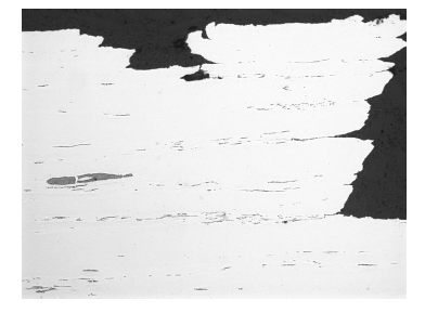
    “Any specimen of steel when examined closely enough will reveal the presence of particles of material incongruent with the metal lattice and demonstrating either definite nonmetallic or quasi-metallic properties.  Some of these are obviously of foreign origin and are entrained particles of refractory, slag and the like, that have been entrapped by the freezing steel.  These are called exogenous, adventitious or accidental inclusions.  Others just as evidently have been precipitated from the liquid or solid metal as a result of chemical reactions or of solubility changes caused by varying temperature.  Such inclusions are known as indigenous, natural, or native inclusions and must be considered an integral part of the heterogeneous and complex material known as steel.  They are as much a part of steel as seeds are part of a fruit.

    inclusion1

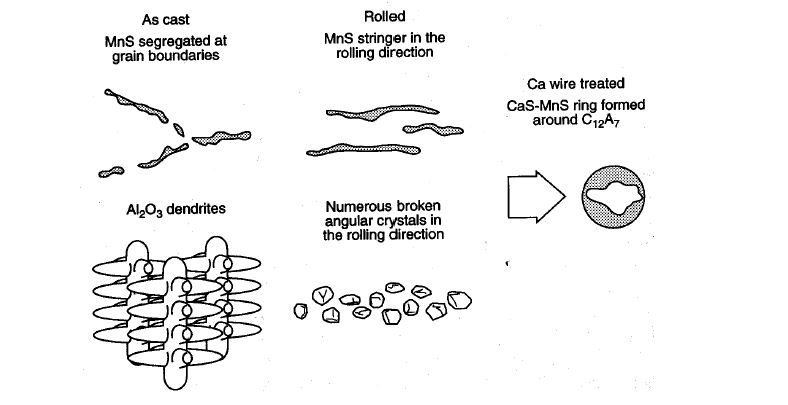
    These days, along with the popularity of seedless grapes, many steel customers have requirements for steel with a minimum volume fraction of inclusions and length of inclusions.  Various properties are adversely affected by inclusions; including impact properties, hot fatigue strength, hot workability, and formability.  Especially in forming applications manganese sulphide “stringer” inclusions are detrimental to edge stretching.  For such applications steel with “inclusion control” is often specified.  It is important to note, however, that this term is not equivalent to “inclusion shape control”.  The former requires the steel producer to lower the Sulphur content of the steel whereas the latter requires the steel producer to modify the shape of sulphide inclusions so that they are less damaging.  Inclusion control is accomplished through various practices in the refining and continuous casting operations.  Inclusion shape control is commonly achieved by calcium treatment.
    inclusion2

    Calcium is generally added to steel in a stabilized form such as calcium silicon, delivered via cored wire, using a wire injection system.  This is normally done in the ladle after trim additions and argon rinsing.  Calcium is a powerful deoxidizer and desulphurizer and thus has two beneficial effects.  The first is that it reduces the total number of inclusion remaining in the steel and the second is that it modifies the shape of the remaining inclusions into more globular ones that are less detrimental to the properties of the final product.

    As steelmaking quality has improved “inclusion controlled” steel has become cleaner and often just specifying in this manner is sufficient for many applications.  An example of such a specification is ASTM A1011 HSLAS-F (where the “F” designates improved formability).  In applications where “inclusion shape control” is known to be required special care must be taken to specify this even where the governing standard does not refer to it.

  • r-Value and Related Parameters

    by Esther Mar | Nov 16, 2017
    • An important parameter which was not discussed in the module on tensile testing, because it is not a direct result of a standard tensile test, is the r-value. It is, however, obtained using a tensile test coupon in a variation of the test.
    • The r-value, the “plastic strain ratio” of sheet metal intended for deep-drawing applications, is a measure of the resistance to thinning or thickening when subjected to either tensile or compressive forces in the plane of the sheet i.e. it is the ability to maintain thickness as the material is drawn.
    • The r-value is the ratio of the true width strain to the true thickness strain at a particular value of length strain (strains of 15-20% are commonly used for determining the r-value of low carbon sheet steel).
    • Due to the difficulty in measuring thickness changes with sufficient precision, in practice an equivalent relationship is commonly used, based on length and width strain measurements.
    • Specifically the tensile coupon is pulled to a specified strain, the machine is stopped and unloaded, and a calculation is made using the original and final lengths and the original and final widths of the coupon.
    • The r-value is often different in the longitudinal, transverse and 45° directions and these relationships are different for different sheet products
    • A material that exhibits unequal properties when tested in different directions is said to be anisotropic. Anisotropy is caused by mechanical fibering due to the directionality of the rolling process. Anisotropy is, more importantly, also caused by preferred crystallographic orientation or “texture” in the steel.
    • Using the r-values in the three directions, two other important parameters are calculated.
    • Delta r (∆ r) is called the “planar anisotropy parameter” in the formula:

      ∆ r = (r0 + r90 - 2r45)/2

      This is an indicator of the ability of a material to demonstrate a non-earing behavior (lower is better).

    • rm, also called r-bar (i.e. r average) is the “normal anisotropy parameter” in the formula:

      rm =(r0 + r90 + 2r45)/4

      This is an excellent indicator of the ability of a material to be deep drawn (higher is better).

    • A combination of high rm and ∆ r provides optimum drawability.

    rvalue1

    Anisotropy values are evaluated from this tensile sheet specimen.

    A strain of 15% is imposed on the specimen.

    rvalue2

    Planar anisotropy is determined with the aid of specimens

    cut at various angles to the rolling direction.  Normal anisotropy

    is equal to the average of anisotropy values around the surface of the sheet.

  • Splitting at a Sheared Edge

    by Esther Mar | Oct 24, 2017

    Many breakage problems are created by tension along a sheared edge or flange.  Some of these problems are caused by a burr due to stamping dies that are dull or have incorrectly set clearances.  When the burr, which has low ductility, is subjected to high strain, as can occur during forming, a crack may develop.  If the crack occurs in an area that is not subsequently trimmed off the result is scrap or rework. Removing the burr will reduce the length of the crack but may not eliminate it.  This is because even though the area where the greatest amount of cold work, the burr, has been removed, severe deformation of the grain structure may extend well into the base metal and reduce the ductility of that area as well.  To eliminate tearing of the blank during forming, the burr and cold worked area must be completely removed or, preferably, be prevented from developing.  This can be done by keeping the dies sharp and adjusted.

    Sometimes even good edges are susceptible to splitting.  In this case it is worth reviewing the part and blank design.  Part designers often have latitude in specifying the final shapes of stampings but even where that is not possible blank shape optimization may be possible by conducting a forming severity analysis.  Based on the part geometry and material properties a finite element model can be developed for the forming stage and analyzed to assess the effect of blank shape redevelopment in minimizing edge strain at the location of the splits.

    splitting1
    Examples of splitting at a stretched edge or flange

    splitting2
    Schematic cross section of a sheared or blanked edge

    splitting3
    Photomicrograph showing a cold worked microstructure in the fracture portion of the blanked edge

  • Pressure Markings on Prepainted Products

    by Esther Mar | Sep 28, 2017

    Pressure marking (or pressure mottling) is an uneven gloss pattern on the surface of a prepainted coil.  It is generally caused by dissimilarity in the gloss and in the roughness between the top and bottom surfaces of a coil.  These gloss differences are transferred with time and pressure to either surface.  Pressure marking is not a degradation of the paint surface except in extreme conditions.  The irregular pattern is typically temporary and will dissipate with time and exposure to heat or ambient temperature.

    In the mechanism by which pressure marking occurs, the gloss components, which are under normal suspension within the topcoat and are random in directionality, are suppressed or flattened within the topcoat under the pressure of coiling. 

    Coil coaters use various best practices related to the backer specification, rewind tension and coiling temperature in order to minimize pressure marking.

    Pressuremarkings1